
weBoost Installation: Campervan Project #7
During Season One, finding a reliable internet connection was a challenge for us while traveling on the road. Since Left Buddy (LB) relies on a good internet connection to get his work done for his consulting business, we decided to install a weBoost signal booster to improve our chances. While we had the solar panels detached from our van roof during the weBoost install, we also raised the panels a little bit to give our MaxxAir fan a little more clearance.
For those of you unfamiliar with weBoost (paid link), it is a device to amplify a cell phone signal. There are three parts to the weBoost. There is an outside antenna, normally roof mounted, that receives a cell tower signal. The second part is a booster unit which takes the signal received by the outside antenna and amplifies it. The last part is an inside antenna which takes the amplified signal from the booster and broadcasts it inside the vehicle. Thankfully, the process works in reverse too so the outgoing connection can get some amplification to make it back to the cell tower.
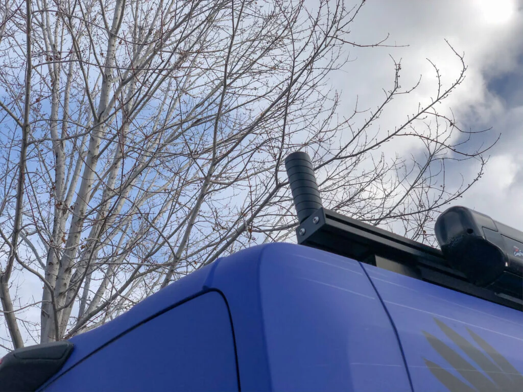
Our first step of the installation process was to mount the outside antenna to the roof of our van. We chose to mount it to the roof rack near the back of the van on the passenger side. We used a small bracket to attach the antenna to our t-track roof rail. Since the outside antenna is now the new highest point on our van, we measured how high the top of it is off the ground so we know what low underpasses to avoid. Our van is now 9 foot 10 inches tall, so we should avoid driving under anything less than ten feet tall. Right Buddy (RB) made a new "our height is" label for the driver’s side windshield corner to be a future reference and reminder.
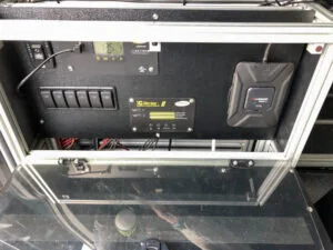
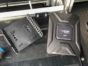
In an attempt to minimize the amount of wires that needed to be run inside the van, we decided to mount the booster inside the existing VanDOit electrical box and locate the inside antenna on the shelf just behind the electrical box. There was ample space to mount the booster inside the electrical box to the right of the rocker switches and electrical displays. Running the connection from the inside antenna to the booster was simple, at least compared to the power connection, and the connection between the booster and the outside antenna.
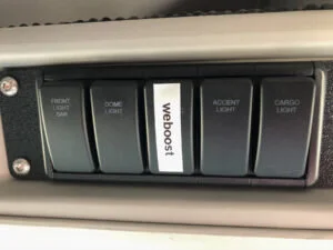
For power, we were hoping to run it from one of our unused rocker switches so we could easily power the weBoost only when needed to save power draw. Previously during our Espar heater installation, we discovered the connections from the rocker switches are not that easy to follow. The rocker switches are connected to a programmable controller and then colored wires run from the controller out to other areas of the van behind the walls. However, as we poked around inside the electrical cabinet, we discovered a blue wire leading from the controller that was not connected to anything. Some simple testing with a multimeter revealed that it was for the rocker switch labeled “DC electric” which we knew was not being used in our van. Hurray! We connected the blue wire to the red wire of the booster's 12V wiring harness with inline fuse. The black wire of the wiring harness simply connected to a lug of the 12V negative wiring block nearby. A simple “weboost” label over both of the DC electric rocker switches (one inside the electrical cabinet and the other above the driver’s head in the front) helps us remember which switch to use for the weBoost power.

The trickiest part of the whole install was running the wire between the external antenna and the booster. Bringing the wire from the outside to the inside required drilling a hole through the roof of the van. Once the wire was on the inside of the van, we wanted it behind the headliner as much as possible without having to remove any t-track. So we drilled the hole in the roof above the electrical cabinet, near the existing holes for the solar panel and powered awning wires.

There is a seam between two headliner panels close to the newly drilled hole. With the help of our nephew, Jeff, we were able to pull the headliner away from the van ceiling enough to feed the wire through and over to the side of the van. Since the entry gland we were using allowed for two cables or wires, we were hoping to run an extra cable for future use. However, we couldn’t manipulate the volume of two wires in the roof structure channel we happened to find ourselves in, so we settled for just running the one wire that we needed.

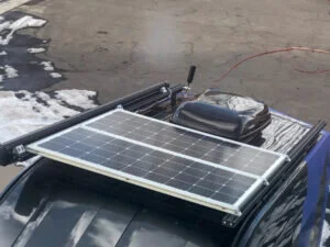
Instead of cutting off the extra length of cable that we didn’t need, we just coiled it up on the van roof. This avoided having to reattach the connectors back onto the cut cable. To make the hole in the van roof waterproof, we attached a double cable entry gland (paid link) and sealed the edge with lap seal (paid link). From the hole in the roof, we ran the cable behind the headliner over to the side where we cut a hole in the edge of the headliner, then ran the cable inside of wire loom, down the side of the plastic trim to the electrical box.
When we drilled the hole in the roof for the weBoost cable, we had to detach the solar panels from the roof. While we had the solar panels removed, we took the opportunity to attach another layer of t-track to raise the panels by 1.5 inches (40mm). Our MaxxAir fan is located under the solar panels and up to this point the lid on it was barely able to open. The original mounting of the solar panels only allowed the fan cover to raise about an inch. We decided that allowing the fan cover to open more would greatly increase the fan's effectiveness. The original install of the solar panels used three pieces of 40 series t-track. Each end of the t-track was bolted through from the top into the black anodized t-track roof rails. To raise the setup, we just added three pieces of t-track to match those of the solar panel framework and drilled holes through them for longer top securement bolts to pass through. So six 8mm x 80mm x 1.25 pitch bolts (paid link) replaced the 40mm ones that were originally needed. To eliminate the sharp edges of the ends of the now exposed t-track ends and for a cleaner look, LB fashioned square end caps out of flat bar aluminum stock. Tapping 8mm threads into the center of the t-track ends allowed for attaching the end caps.
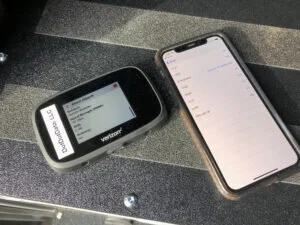
After everything was installed, we ran a simple test in our driveway. Before turning on the weBoost, we were getting an RSRP (Reference Signal Received Power) reading of -107 dBm for our Verizon Jetpack and -112 dBm for our AT&T signal on our iPhone. Both of these readings are considered to be in the “Fair” range (Making Sense of Signal Strength). After turning on the weBoost, we saw RSRP readings of -87 dBm for Verizon and -105 for AT&T. So, the Verizon signal strength moved up to the "Excellent" range and the AT&T signal strength moved up to the “Good” range. Keep in mind this was not a very extensive test, but the weBoost appears to be working.
We’ll keep you posted on how well the weBoost is helping with our internet connections as well as if we notice an improvement in airflow using the fan with the raised solar panels. Stay tuned!
Check out our related video: weBoost Installation
(RB)