
Espar Heater Installation: Campervan Project #6
When we were finalizing our VanDOit camper van build, we chose not to include the Espar heater. Cash was a little tight last year and our plans for the summer did not include camping in cold temperatures. Since our travel plans for 2020 include camping from March to November, we decided we needed to install the Espar heater. This blog explains our installation experience and the challenges we faced.
LONG SAFETY WARNING: This is NOT an instructional or “how-to” for installing an Espar heater. Installing it in a completed VanDOit van is not a simple DIY project. We do not want to hear about anyone who was injured or damaged their van because they were following what we did. Our recommendation is to let VanDOit install it during your build. If we lived closer to the VanDOit factory, we would have had them install it, especially after learning how difficult it is and how long it took us to do it. We are only documenting what we did for our installation of an Espar Airtronic B4L heater in a 2018 Ford Transit passenger van converted to an RV/Gear Hauler by VanDOit. Do your own research, evaluate your own capabilities, and make your own decisions if you attempt such a project. Consult professionals if you have any questions with products and installation. We are not professionals in this subject matter. We would not recommend this project to just anyone. If you’re not willing to research expert sources, source your own supplies, use saws and drills, touch an electrical system, spend time on your back under the vehicle occasionally in contorted positions, lower your fuel tank, and attach a fuel line to the tank, then this project is not for you. That said, if you like being hands on and don’t mind what’s involved, this is a doable project. There are various Youtube videos of similar installs though we didn’t find one for our specific heater nor one in a Ford Transit.

For those that aren’t familiar with heaters like this Espar (or Webasto or similar), these are small heaters mounted somewhere inside your vehicle that are fueled directly by your fuel tank. Separate heater models are made for gasoline and for diesel fuels. The fuel is burned inside the unit, and thus inside the vehicle, but its combustion chamber uses a hose to pull combustion air from outside the vehicle and a pipe to push the exhaust outside the vehicle. This keeps the air inside your vehicle safe. To heat the air in the vehicle, the heater unit pulls air from inside your vehicle through one end of the unit, passes the air over the combustion chamber where the air gets heated, and then pushes the heated air out an exhaust port and ductwork into the van.

To add an Espar heater to our van we basically had three options:
Take the van back to VanDOit. This would involve a 10 hour drive each way, a few nights stay in the KC area, and an estimated $3000 price tag. (This value may not be accurate as we did not ask them for a quote. The price is based on if we added the option as part of the initial build).
Find a local professional to install it. Again, we’d have to give up our van (our main daily driver) for a few days in the shop. Quality local resources and rates are unknown.
Take on the project ourselves. Always the cheapest option provided everything goes as planned, we have enough available time, and the quality of work is something we are capable of.
Obviously, we chose option 3. Left Buddy (LB) likes hands-on projects, has exposure to many trades, and has glimpses of being somewhat handy. Plus, how hard can it be? ;-)

We ordered the Espar / Eberspacher Airtronic B4L M2 (Petrol) 12v (4kW) Heater Kit from Heatso.com for $1453.77 including the controller, a floor mounting bracket, and shipping. The kit comes with:
Espar Eberspacher Airtronic B4 12v Heater
12 V Fuel Pump
Fuel Hose
Exhaust Silencer (muffler)
Electrical Harness
Stainless steel exhaust pipe
Fuel Standpipe
Combustion intake pipe
Flexible ducting
Inlet / Outlet grills
Air outlet
Screws, clips and plastic straps required for installation
Installation manual (rather hard to follow and minimal)
Warranty documentation
EasyStart Pro Timer ($119.99)
Floor Mounting Bracket ($33.79 which turned out to not be necessary for our installation)

Other materials that we purchased for the install include:
Series 25 T-track from Grainger for the heater enclosure structure. (~$45 for a 13' length)
1/4” (6mm) ABS HairCell Black textured sheet material sourced locally from Colorado Plastic Products. ($100.89 for a 4’ x 4’ sheet. Only a portion of the sheet was required for the heater enclosure, but we plan to use remaining plastic for other van projects)
Various hardware (such as T-nuts, economy t-nuts, L-brackets, and machine screws) from Grainger and Amazon
Ford Auxiliary fuel line port (part # CK4Z-9B210-A. ~$35 after shipping from OEM Ford Parts)
Plastic 5/16" to 1/8" reducer (8mm to 4 mm) for fuel line (paid link)
Pro Seal Red Hi-temp RTV Silicone Instant Gasket (paid link)
Shurtape AF100, 181A-P/181B-FX foil tape (paid link)
Rust-Oleum protective enamel (paid link)

We also purchased some tools specifically for the heater installation:
Multi-step hole drilling bit (paid link)
Wire crimping and connector supplies
Protective wire loom (paid link)
Wire clamps (paid link)
Hole saw (paid link) - we used 1 1/8" hole saw, but a 1" would have worked better
10" Aluminum-cutting saw blade for our miter saw (paid link)

The Espar heater is mounted inside the vehicle and the fuel pump is mounted underneath the vehicle. There are several holes that need to be drilled through the floor of the vehicle. Four holes are for the mounting bolts. There are two large holes, one for the air intake hose and one for the exhaust pipe for the combustion chamber. There are two small holes that are for the fuel pump, one is a fuel line from the fuel pump to the heater and the other is for the electrical power from the heater to the fuel pump. There are several electrical connections that need to be run inside the van from the heater. There is a power connection for the controller (5 amps) and another connection (20 amps) to power the heater itself (for the fan, ignition, and fuel pump). The last electrical connection is from the heater to the controller, in our case, the EasyStart Pro Timer.

The first challenge we faced was where to place the heater in the van. Most internet videos show the Espar heater being installed under the front passenger seat. However, our VanDOit van is built on the Ford passenger van, not the cargo van, and the space under the front passenger seat is taken up by the factory blower motor for the rear passenger floor vents. VanDOit installs the Espar heater under the third row of seats against the driver side van wall, at the end of the T-track shelves (and partially overlapping with the shelves) under the bed platform.

We thought about how heat rises and how we wanted to make sure the heat was concentrated in the living area (the area to the front of the bed/cargo area), and the bed at night. Putting it under the bed would make it hard for the warm air to flow around the bed to get above it where we sleep. Also, there are things in the way for the air to flow from the cargo area into the living area, like the electrical cabinet. So installing it where we saw VanDOit put it made the most sense to us. However, VanDOit installs the heater with the heated air outlet directed towards the front, but our fridge stand would block that air flow. To solve that issue, we decided to direct the air flow out to the side, to blow through the opening of the leg supports of the factory bench seat.

The plan was to build an enclosure for the heater out of T-track and black plastic, similar to what VanDOit uses. In order to make sure the dimensions of the enclosure would work, we mocked it up using scrap plywood. With the mock enclosure positioned in the van, we put the bench seat in and then took the bench seat back out, making sure the enclosure did not interfere with the process. The mock up told us the maximum height and width that our finished enclosure could be. While the bench seat was in position, we located where the heated air outlet should go on the enclosure.

The next tricky part was figuring out the exact placement of the heater inside the enclosure in the van. When we looked under the van in the general location, we discovered quite a few van structural elements that we needed to avoid. Relating the front to back locations from the inside of the van to the outside of the van involved marking a spot on tape on the van window that we could see both inside and out, dropping a vertical line and measuring from there. However, relating the side-to-side positions between the inside of the van to underneath the van was not as simple, since we did not have an accurate idea how thick the van wall was.

There was a rectangular space on the underside that we knew we needed the hoses and mounting bolts of the heater to fit within. We were trying to avoid making more holes in the floor of the van than was necessary, but we ended up drilling a couple of pilot holes, one in each corner of the rectangular space furthest from the side of the van. We then knew we needed to mount the heater between those two pilot holes and the side of the van.

It was at this point that we realized we had to change the design of the enclosure. The position of the holes for the heater were closer to the van wall than we thought and did not leave enough room to run a complete rectangle of T-track around the base of the enclosure. The solution was just to leave that one section of T-track out. There seemed to be enough structure left to provide enough support.

We now had enough information to cut away the flooring down to the metal of the van on the inside to match the position and size of the heater enclosure. A hole saw was used to quickly see if there were things to avoid under the wood floor. After cutting away the remainder of the flooring with an oscillating saw, we taped around the perimeter of the rectangular hole with foil tape to stop air flow or small items from going under the floor.

There is a rubber gasket on the bottom of the heater which surrounds all the hose and mounting holes (but not the one for the electrical connection to the fuel pump). The gasket is easily removed from the heater and makes a great template. However, how do we determine exactly where to place it on the floor of the van? It is hard to accurately measure the position of the gasket on the heater because all of the surfaces of the heater are curved and not flat.

The solution was to create a template of the heater out of cardboard. Using the gasket, we traced around the outside of it and cut out the oval. The oval base of the heater fit perfectly down into the hole in the cardboard. Then, using a speed square to determine a perpendicular line from the outside edge of the heater, we traced the outline of the heater onto the cardboard. After that it was simple to cut out and position it on the floor of the van to make sure the heater would fit within the desired space.

After we determined the position of the gasket, we used it to trace out the positions of the holes. For the two large holes, we used a hole saw drill bit of the proper size. After drilling all of the holes including the one for the electrical wire to the fuel pump (which is separate from the holes in the gasket), we smoothed out the rough edges with a metal file and primed the bare metal with Rust-oleum enamel to prevent rust. After bolting the heater into place inside the van, we turned our attention to underneath the van.

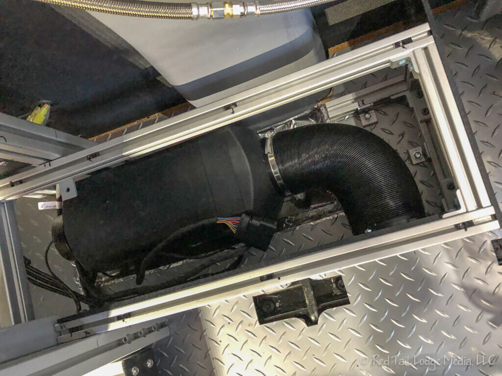
We ran the exhaust pipe, along with the silencer (muffler), towards the front of the van from the heater and ran the combustion air intake hose in the opposite direction so that exhaust fumes would not enter the air intake. The open end of both hoses point downward to allow condensation to drain off. The exhaust pipe gets hot, so we needed to make sure it was not running near anything that could not take the heat, like fuel lines, electrical wires and brake hoses. After mounting the fuel pump, we ran the fuel line and electrical line from the heater to the fuel pump. We had trouble reading which side of the fuel pump electrical connector each wire should go into. We finally saw the small number 1 and 2 printed on the plastic connector; it was really hard to see and read (or maybe our eyes are just old). Finally we used Red Hi-temp RTV Silicone Instant Gasket to tightly seal all the holes in the van floor.

Then we focused on finishing the heater enclosure. We built the box out of T-track and black plastic. The black plastic turned out to be pretty easy to work with. The enclosure is connected to the floor and to the existing T-track shelves under the bed. A hole was cut in the black plastic for the heated air outlet. We cut the hose to fit from the heater to the hole in the black plastic and then mounted it in place. The magnetic retriever tool came in handy when nuts were dropped that slid into tight spaces underneath the heater.

To complete the enclosure, we made a top out of the black plastic. One piece covered the enclosure up to the existing T-track shelves and another piece for inside the existing T-track structure which no longer had the end plastic piece in place since the heater extends into what was previously dead space. The initial size of the plastic was cut using a table saw. We used a metal contour gauge to trace the edge to fit snugly against the side of the van, to prevent items from falling down into the enclosure. The shape was then traced out on the plastic and cut using a jigsaw. The plastic is easy to saw, drill, and sand and is not brittle.

The factory edge of the plastic sheeting was not smooth for some reason, so a jointer was used to clean up the edge. We also used the jointer to slightly change the angle of the edge of the plastic so it would line up better with the T-track frame angle that was nearly, but not quite square. By attaching a few layers of tape to the end which did not need to be trimmed, the angle that the plastic went through the jointer slightly changed and gave us the trimming that we needed. We used a drill press to make the holes in the plastic needed to mount it to the T-track. For the smaller plastic piece to go inside the existing T-track structure, we again used the metal contour gauge, this time to trace around the housing for the bed platform hydraulics.

Next we worked on the electrical connections inside the van. Instead of running the electrical wires through the ceiling (which would require pulling down the ceiling T-track in order to pull down the headliner), we ran the electrical from the heater to the electrical box (on other side of the van) along the floor just below the cargo slide. Some split loom tubing packaged the two wiring bundles nicely. One wire bundle was for the heater controller and the other bundle was the power for the heater and controller which split into a wire for the 5 amp circuit, a wire for the 20 amp circuit, and a ground wire.

The plastic connector on the power bundle was too large to fit under the T-track to get to the space under the gear slide. So we cut it and tried to splice it back together. We first tried soldering it back together, but our old soldering iron would not get hot enough. Then we tried crimp connectors, but we couldn’t get them to hold. Perhaps we had the wrong size connecter for the size of the wire? Then we borrowed a soldering iron from a neighbor and soldered it back together. We protected the connection with heat shrink tubing using a hair dryer, followed by electrical tape.

We mounted the controller (EasyStart Pro Timer) on the side of the van just above the electrical cabinet using the sticker pad that came with it. We would have liked it mounted up above the sliding door, next to the air conditioner controls, but that would have required making holes in the headliner to mount it and possibly for running the wires as well, which we did not feel comfortable doing since we didn’t know exactly what was behind the headliner. In order to ensure no damage to existing wires behind the headliner, we would have to pull down the t-track and headliner which we wanted to avoid.

Initially we were hoping to connect the power for the heater through one of our unused rocker switches. However, after opening up the electrical cabinet, it did not look like a simple thing to accomplish. The rocker switches connect to a programmable control unit before becoming a large tangle of colored wires in a tight space leading out of the electrical box. Not fully understanding the system, we opted not to open that can of worms. Instead, we connected the heater power to a couple of open ports on the DC fuse bar. The yellow fuse in the picture is the 20 amp circuit we installed for the heater and the brown fuse in the picture is the 5 amp circuit we installed for the heater controller.

The biggest surprise and challenge of the heater install was finding out the van gas tank needs to be lowered in order to reach the auxiliary port of the gas tank (unlike a Mercedes Sprinter van where the auxiliary port is easily accessible). We don’t own a floor jack, nor a garage tall enough to fit our van into, nor a flat driveway to work on. Luckily we know someone who owns a floor jack and was willing to let us borrow it. We also have a nephew, Jeff, who is a retired Air Force mechanic, willing to come out and help us at a moment's notice when the weather was nice enough to work outside.

Leading up to the day when we lowered the gas tank, we were careful to keep the gas tank less than a quarter full to reduce the weight of the tank. We had about five gallons of gas in the tank at the time we lowered it which should have weighed about thirty pounds. The tank itself is plastic so we’re guessing the whole thing weighed less than fifty pounds. In order to get the van more level than our driveway, we drove the two wheels on the passenger side up onto the curb/sidewalk leaving the other two wheels in the street.

There are three metal straps bolted to the underside of the van that hold the tank in place. The tank is on the driver’s side of the van, so three of the six bolts were somewhat easy to get to, but the other three where in the middle of the van. It was a rather tight squeeze to get under the van on the curb side and reach the remaining three bolts. LB was in an awkward position when trying to loosen those bolts and felt something “pop” near his rib cage. The pain of that, whatever it was, took about a week to go away.

A floor jack along with a small piece of plywood was used to support the weight of the gas tank while the metal straps were removed. Jeff and LB then lowered the tank just far enough to reach the auxiliary port on top of the tank, being careful not to stress the fuel hose connected to the tank. Six inches or so was all the farther that our setup would allow the tank to lower, but that was just enough to work with.

It was hard for LB to see what he was doing as he felt around the top of the tank. With the help of phone pictures so he could visualize where things were, he was able to finally remove the auxiliary port plug (with the yellow plastic in the picture) and replace it with the Ford Auxiliary fuel line port. LB had already connected the fuel line encased in split wire loom tubing to the Ford Auxiliary fuel line port before the tank was lowered to make it easier. Then it was just a matter of raising the tank back up and bolting the straps back into place. The process of lowering the tank, making the connection, and raising the tank was fairly smooth and took about 45 minutes.

As the daylight was dwindling and the temperature outside was dropping, Jeff and LB completed the final step by connecting the fuel line running from the auxiliary port to the fuel pump, attaching it to the frame of the van in a few places with a variety of zip ties and stainless steel clamps.

The Transit auxiliary port cannot pull fuel when the gas tank is below a quarter full, so we didn’t test out the heater until the next day when we got the chance to fill the tank. Priming the heater fuel line for the first time can take a few cycles of the heater startup so we waited anxiously for several minutes, listening to the clicking of the fuel pump, waiting for the heater to turn on, and warm air to flow out the vent. Lo and behold it worked! We let it run for thirty minutes to burn off the manufacturing oils.

In summary, it took us almost forty hours of work (including all the research and online orders and supply runs) over about two months of elapsed time and cost us approximately $2200. Was it worth it? Given that we were unable to include it in our initial build, yes! If we had the money during our initial VanDOit build, would it be worth the extra money to have them do it? Absolutely! It would have been better to have wires run under the headliner than what we did and saved us a lot of time and pain. Will this blog help you decide what you should do? We hope so! If not, we at least hope it was interesting or entertaining.
Check out our related video: Espar Heater Install: Campervan Project #6
(RB)